
Get your motor drive
to production faster.
Space efficient servo modules with custom carrier board design
Designing a motion control system around a servo drive module is faster and lower-risk than a full custom drive design — if you have the right integration partner. POWER&D supplies Ingenia servo drive modules directly and designs the carrier board, power stage, and EMC compliance around them. One partner, from component to certified hardware.
2-3 months
Typical design-to-prototype timeline
3kW+
Rated output – Everest S NET at 80V bus
99%
Module efficiency – Everest S NET at rated output
The module solves the hard part.
Getting it into your product isn't.
01Carrier board design
Application-specific PCB with correct connector placement, power pin routing, mezzanine interface layout, and thermal relief — designed by engineers who understand power electronics, not just PCB layout.
Ingenia's servo drive modules are production-proven and well-documented. What most engineering teams underestimate is the integration work between the module and a shippable product.
04Feedback interfaces
Differential encoder signal conditioning, resolver interface electronics, Halls, SSI, BiSS-C — designed for your sensor hardware with correct termination and noise immunity.
02EMC compliance
Conducted emissions filtering, ESD and surge protection, and layout decisions that hold up in a pre-compliance EMC test — tested in our own lab before your first submission to a notified body.
05Functional safety integration
STO input conditioning, functional safety isolation, and braking resistor drive — implemented correctly so your SIL-3 module actually operates at SIL-3 in your system.
03Power conditioning
DC bus input filtering, inrush limiting, logic supply regulation, and braking resistor control — all matched to your bus voltage, load profile, and enclosure constraints.
06Design for manufacturing
Component selection for availability, DfM-optimized layout, and series production support — so the first prototype board design is also the production design.
DESIGN FOUNDATIONBuilt on Ingenia's Summit Designer ecosystem
POWER&D works in Altium Designer — the same toolchain Ingenia uses for their own reference designs. That means we can work directly from Ingenia's Altium Integrated Libraries, Device Sheet Modules, and reference project examples, cutting schematic capture time and reducing integration errors. The module's plug-in architecture constrains the problem: instead of designing the entire drive, we design a well-defined carrier board around a production-proven core.
Requirements review
We map your mechanical envelope, bus voltage, motor type, feedback sensors, fieldbus, and safety level. Module selection is confirmed or adjusted here.
Architecture & schematic
Full carrier board schematic in Altium Designer — matching Ingenia's own design ecosystem. Power stage, filtering, feedback, I/O, and safety all reviewed against the module's application notes.
PCB layout & thermal design
Power electronics layout with controlled impedance where required, thermal interface design for the module's case, and mechanical fit-check against your enclosure.
EMC pre-compliance
First-article prototypes tested in our in-house EMC lab before your formal submission. Conducted emissions and ESD performance verified at the board level.
DfM & production preparation
Fabrication package optimized for manufacturing. BOM scrubbed for availability. Production test strategy defined. Series production available on request.
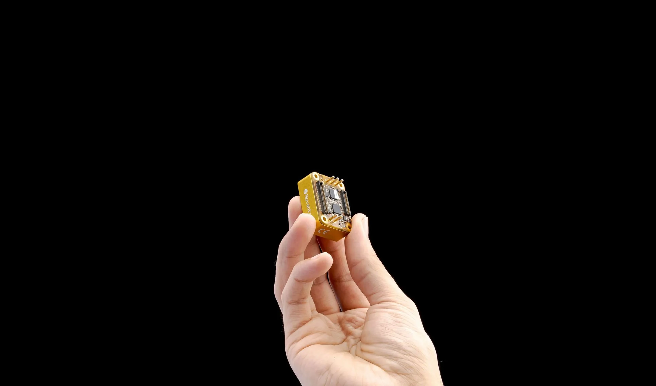
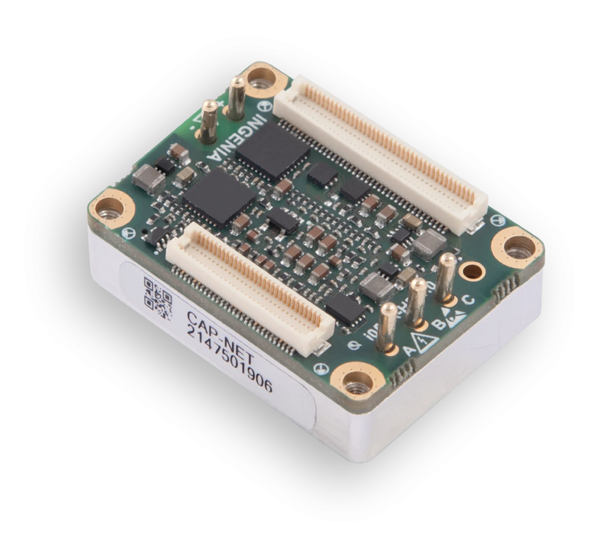
Ingenia servo modules
All three modules share Ingenia's plug-in architecture, designed to be soldered or socketed onto a custom carrier board. We design around whichever module fits your power range, safety level, and form factor.
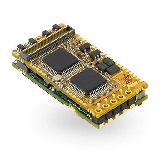
Denali Safe
Communications: EtherCat
Supply Voltage: 8-60 V
Continuous Current: 5 A rated
Peak Current: 10 A (1 s)
Standby power consumption: 1.4 W
Dimensions 33 mm x 17.6 mm x 8.52 mm
Weight: 7 g
PWM Switching Frequency: 20 - 200 kHz
Feedback: QEI, Halls, Up to 2x absolute encoders (BiSS-C)
Efficiency: Up to 99%
Safety Performance Levels: SIL3 Ple CAT3
Safety Functions (non-feedback dependent): FSoE, STO, SI, SS1-t
Safety Functions (feedback dependent): SS1-r, SS2-t, SS2-r, SOS, SLP, SLS, SSR, SAR, SLI, SDI, SP, SV
Capitan
Continuous Current: 10 A
Peak Current: 20 A (1s)
Supply Voltage: Power: 5-60 V
Efficiency: 99 %
Standby power consumption: 1.12 W
PWM Switching Frequency: 20 – 200 kHz
Supported Motor Types. DC Brushed, Rotary Brushless
Supported Feedbacks: Digital Halls, Digital Incremental Encoder, BiSS-C, Dual Biss-C, Dual BiSS-C Daisy Chained, BiSS-C and SSI, SSI, Dual SSI
Communications: EtherCAT, CANOpen or SPI
Supported Motion Modes: Profile Position, Profile Velocity, Cyclic Sync Position, Cyclic Sync Velocity, Cyclic Sync Torque, Homing
Dimensions 34.5 mm x 26 mm x 10.3 mm
Weight: 18 gr
Functional Safety: STO SIL3 PLe (TÜV certified)
Connectors Pinout: 100% compatible with Everest
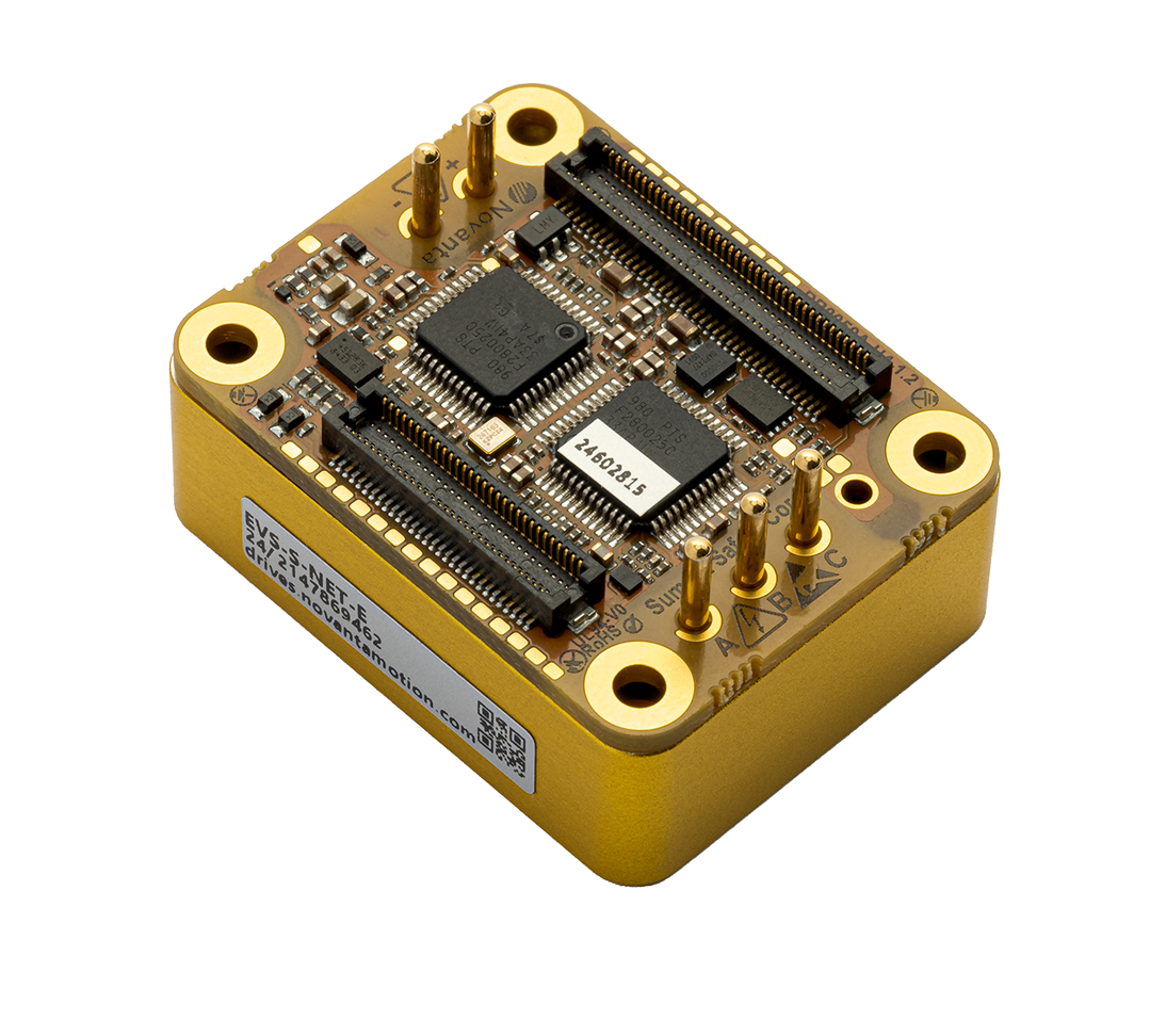
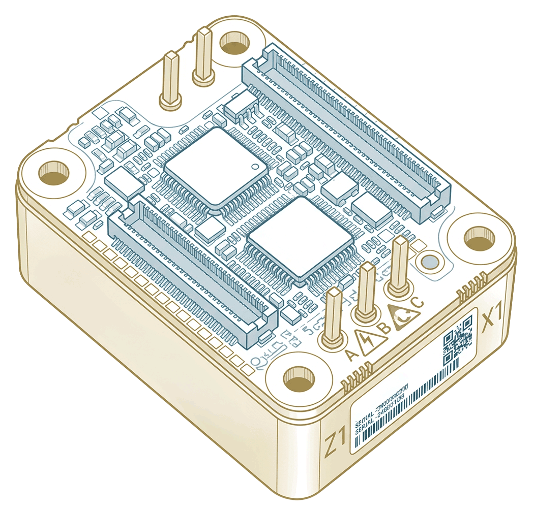
Everest S Safe
Communications: EtherCAT
Voltage: 8-60 V
Continuous Current: 45 A rated
Peak Current: 60 A (1s)
Standby Power Consumption: 1.9W
Dimensions: 37 x 28.5 x 15.86 mm
Weight: 28g
PWM Switching Frequency: 10 - 100 kHz
Feedback: QEI, Halls, Up to 2x absolute encoders (BiSS-C)
Efficiency: Up to 99%
Safety Performance Levels: SIL3 Ple CAT3
Safety Functions (non-feedback dependent): FSoE, STO, Sl, SS1-t
Safety Functions (feedback dependent): SS1-r, SS2-t, SS2-r, SOS, SLP, SLS, SSR, SAR, SLI, SDI, SP, SV
Power electronics expertise, not just PCB layout
01In-house EMC lab
Pre-compliance testing before your first formal submission means layout issues are caught and corrected at prototype stage, not after a failed accreditation test. Conducted emissions and ESD performance verified on real hardware, in Stockholm.
Several contract design houses can route a PCB. Fewer understand the power electronics, thermal, and EMC disciplines that determine whether that board works in production.
02Power electronics depth
Our engineers work on GaN and SiC motor drive designs, high-frequency magnetics, and DC/DC power stages as core business — not as occasional PCB work. That background directly informs every carrier board decision from input filter topology to gate drive layout.
03Altium ecosystem alignment
Ingenia publishes their reference designs, device sheet modules, and integrated libraries in Altium. We design in Altium. There's no translation layer between the reference material and your carrier board schematic — which reduces integration errors and accelerates the design cycle.
04Nordic and European supply chain
POWER&D is based in Stockholm and part of the Addtech Group — a listed Swedish industrial group with broad European procurement reach. For defense and aerospace customers with European sourcing requirements, this matters.
05Full lifecycle, single partner
Architecture review through series production support without handoffs between design and manufacturing partners. The engineer who designed your carrier board is also available during first article inspection and production ramp.
06Close collaboration
We work iteratively and in close contact with your engineering team throughout the project. Requirements evolve — we'd rather surface that early in a design review than late in a bring-up session. You stay involved, not just informed.
Standard drive modules
Ingenia Everest, Capitan, and Denali modules available directly through POWER&D. If your team handles carrier board design in-house, we supply the module and provide application engineering support to get you started.
Everest S NET and Everest S Safe
Capitan NET and Capitan CORE
Denali Safe NET
MotionLab 3 and Altium library support
Application engineering support included
From off-the-shelf carrier boards to fully custom designs and ongoing production support – structured to match where your project is today.
Three ways to work with us
MOST COMMONCustom carrier board design
When the standard modules alone don't cover it, we design the carrier board around them. Mechanical envelope, bus voltage, feedback sensors, fieldbus, safety level — all specified upfront, then executed in close collaboration with your engineering team from architecture through to first article.
Full schematic and PCB in Altium Designer
EMC pre-compliance testing in our lab
DfM-optimized BOM and fabrication package
First article support and bring-up
Series production supply
Once your carrier board design is validated, POWER&D handles series production — supplying the Ingenia modules, managing PCB assembly, and delivering tested motion drive assemblies ready for integration into your product. One order, one invoice, one point of contact.
Ingenia module procurement and supply
PCB assembly and production management
Functional test and quality documentation
Engineering support for field changes and revisions
Start with a
30 minute technical brief.
Tell us about your application: motor type, bus voltage, safety level, fieldbus, and mechanical constraints. We'll map it to the right module, identify the integration challenges early, and outline what a carrier board project looks like from architecture to first article.